 Business






Kinetic Log Splitter Covers: Fit the Flywheel, Beam, Wedge, and Wheels

Kinetic splitters store energy in rotating flywheels and deliver it [...]
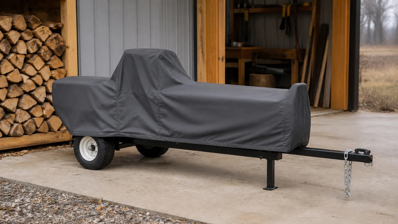
Kinetic splitters store energy in rotating flywheels and deliver it through a rack-driven ram, creating a different profile from many hydraulic machines. The flywheel guard, engine or motor, beam, wedge, work table, handles, wheels, and tow assembly all influence the pattern. Custom kinetic log splitter covers should be measured only when the machine is shut down, cool, clean, stable, and arranged in its approved storage configuration.
Follow the equipment manual before touching or covering the splitter. Disconnect energy sources as directed, remove the key, secure the ram, clear wood debris, and wait for every hot or moving component to stop and cool. A fabric cover is for storage protection; it must be removed before inspection, fueling, charging, transport, maintenance, or operation.
Choose the Approved Storage Position
Record whether the splitter stores horizontally, folds, uses a stand, or remains attached to a tow frame. Lock the beam, table, jack, and handles exactly as the manufacturer specifies. Do not measure a temporary position held by hand or supported with loose blocks. Photograph the control side, wedge end, engine side, and tow end. The final pattern is tied to this configuration and may not fit safely when guards or accessories move.
Measure the Beam and Wedge Envelope
Use straight dimensions following How to Measure. Record overall length, maximum width, beam height, wedge projection, table or cradle width, and the farthest point reached by handles or guards. Do not stretch a tape across a sharp wedge; measure from safe fixed references. Note whether the wedge is fixed, removable, or fitted with an approved attachment, because each version changes the upper profile.
Map the Flywheel and Drive Housing
Measure the outside width, height, length, and offset of the flywheel guard, belt housing, rack shield, and related fixed covers without removing any guard. Identify ventilation openings, service panels, labels, and protruding fasteners. The fabric must not be installed over hot components or used while the machine is running. Allow practical ease around broad housings so removal does not snag a guard edge or pull against a seam.
Document the Power Unit and Controls
Record engine or motor dimensions, fuel cap or battery location, starter, switch box, exhaust direction, and control lever envelope. Gas units must cool completely and follow fuel-storage instructions; battery units must follow charging and battery-removal guidance. Never charge, refuel, or operate beneath a cover. If service access is required during storage, define it carefully rather than cutting an improvised opening that can expose the equipment to weather.
Account for Wheels, Jack, and Tow Bar
Measure tire diameter, outside wheel width, axle position, jack height, hitch projection, safety-chain location, and any transport handle. Keep the hem clear of tires, sharp couplers, and wet ground. Closures must not interfere with brakes, chains, wiring, or inspection points. Remove the cover before towing or rolling the unit, and never treat fabric straps as tie-downs for road transport or as a substitute for wheel chocks.
Plan Drainage Without Loading the Beam
Long horizontal equipment can create a broad flat shelf where water collects. Establish a stable top slope using only supports approved for the machine and compatible with paint and guards. Do not rest makeshift poles on controls, the wedge, or a thin shield. Check the first rain event and remove standing water. If condensation appears, uncover the cool machine, dry it, and improve airflow rather than sealing the lower edge more tightly.
Select Fabric for Work-Site Conditions
Compare UV, water performance, abrasion, cold-weather flexibility, and handling weight on Our Fabrics. Related buyers can browse Equipment Covers. Brush away bark, chips, oil, and grit before covering, using maintenance methods approved by the equipment maker. Sharp metal, damaged guards, and leaking fluids should be repaired first; a cover should not conceal a defect that needs service.
Test the Fit Around Hazard Points
With the machine safely shut down and cool, install the cover and inspect the wedge end, rack area, flywheel guard, engine, controls, wheels, hitch, hem, and closures. Use a front label so the cover is not dragged backward across the wedge. After a weather cycle, check paint contact, trapped debris, moisture, and seam tension. Stop using the cover if it obstructs labels or must be forced over a sharp projection.
Create a Storage and Inspection Log
Assign the cover to one asset and record installation, weather exposure, cleaning, and any fit change. Inspect tires, guards, fasteners, handles, the wedge, and the cover’s internal contact zones before long storage. Dry fabric fully before folding it away. Re-measure after fitting a work table, changing tires, replacing a guard, or modifying the tow assembly, because even a small projection can change the safe removal path.
Prepare the Splitter Order Record
Send the model, approved storage position, overall envelope, beam and wedge details, flywheel housing, power unit, controls, wheels, tow assembly, exposure, quantity, and labeled photos. Review Kinetic Log Splitter Covers and use Request a Quote for attachments or folding frames. Fleet and rental buyers can coordinate repeat specifications through Business Inquiries. Verify every dimension against the actual unit.
Share This Article

Written by : CoversForge
Follow Us
Latest Articles
September 9, 2026
September 9, 2026