 Business


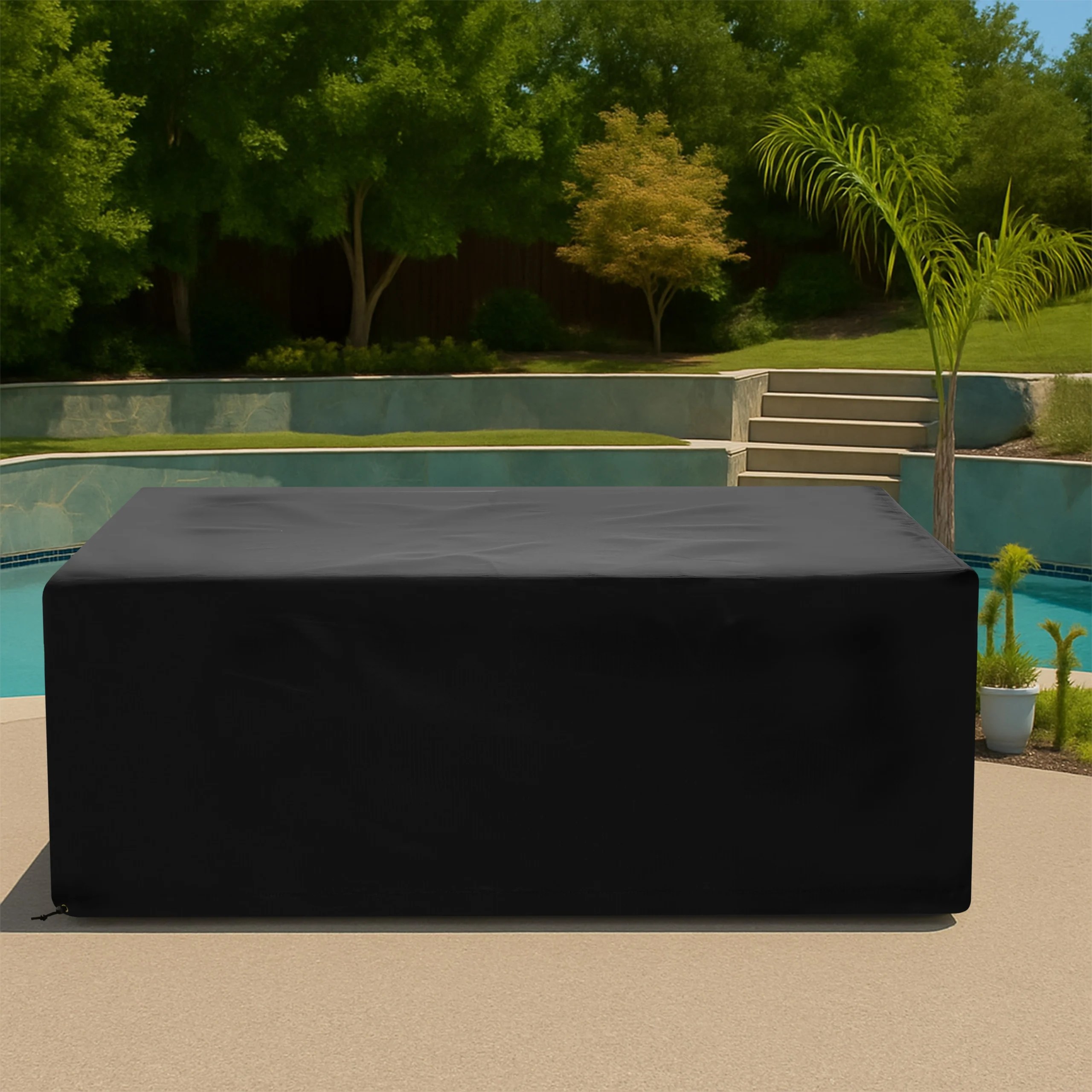




Pool Lift Covers: Measure Arms, Controls, Anchors, and Moving Parts

A pool lift combines a seat, arms, controls, moving joints, [...]

A pool lift combines a seat, arms, controls, moving joints, support column, drive components, and an anchored base in a compact but irregular assembly. A custom pool lift cover can protect idle equipment from sun, dust, debris, and poolside exposure while fitting the actual stored position more closely than a general-purpose bag.
Accessibility and safety come first. The cover must be fully removed before the lift is used, must not block the accessible route, and must follow the lift manufacturer’s inspection, charging, clearance, and storage instructions. Protection should never make the equipment harder to find, inspect, or deploy.
Document the Manufacturer-Approved Stored Position
Place the lift exactly as the manual directs for storage: seat raised or lowered, armrests positioned, footrest secured, and rotation locked if applicable. Record whether the chair faces the pool, deck, or parallel to the edge. A pattern made for one position will not fit safely when the lift is rotated or partially deployed. Include the model number and manual references with the quote so dimensions can be discussed in the right operational context.
Measure the Seat, Arms, and Footrest Envelope
Measure overall seat width, back height, cushion thickness, armrest span, and the farthest reach of the footrest. Include belt hardware, headrests, removable accessories, and any hand controls stored on the chair. Do not pull fabric tight across delicate controls or padding. The cover needs removal allowance around the widest points while remaining compact enough that it does not sag onto the pool deck.
Map the Column, Motor, Battery, and Controls
Record support-column height and diameter, motor housing dimensions, battery pack location, charging port, control box, emergency stop, pendant holder, and any exposed wiring channels. Access requirements vary by model. A shaped column section and marked access flap can support visual inspection during storage, but the cover still needs to come off for operation, charging, service, or any check required by the manufacturer.
Photograph Moving Joints and Pinch Areas
Show pivot points, rotating arms, hinges, actuator rods, and the clearance between the seat assembly and support column. The pattern should not add straps or seams that can catch in moving parts after removal. A clear front label and consistent closure direction help staff take the cover off completely and move it away from the operating zone before a guest uses the lift.
Measure the Base Without Obstructing the Deck
Record anchor-plate dimensions, bolt height, pedestal shape, and the distance from the pool edge. The finished hem should stay clear of walking surfaces and should not conceal a loose anchor or maintenance issue. Use How to Measure for the basic envelope, then add a top-down photo that shows the accessible route, coping, drain locations, and nearby rails.
Plan for Pool Water, Chemicals, and Sun
Splash, humidity, ultraviolet light, cleaning products, and airborne pool chemicals create a demanding environment. Rinse and dry the lift as directed before covering, and never seal wet surfaces beneath fabric. The cover can reduce direct exposure during idle periods, but it cannot replace corrosion inspection, battery care, cleaning, or the maintenance schedule required for accessibility equipment.
Choose a Visible, Manageable Fabric
Pool staff may remove and reinstall the cover frequently, so handling weight and visibility matter. Compare suitable materials on Our Fabrics and choose a color that is easy to recognize against the deck. Secure closures should withstand wind without wrapping around the anchor or moving assembly. The removed cover needs a designated storage place where it cannot create a trip hazard.
Design Access Without Encouraging Covered Operation
Inspection flaps can expose a battery indicator, control housing, or identification plate during storage, but access should never suggest that the lift can operate while covered. Keep the closure obvious, position it away from pinch zones, and specify a full-removal checklist for staff. Hotels and aquatic facilities can add identification so each cover returns to the correct lift after cleaning.
Create a Staff Removal and Storage Checklist
Before opening the pool, staff should inspect the deck, release every closure, remove the cover completely, and place it in its designated dry storage location. Confirm no strap, flap, or loose cover remains near the anchor, transfer route, water edge, or moving assembly. Then complete the lift manufacturer’s required operational inspection before making the equipment available. At closing, reverse the process only after the lift is clean, dry, returned to its approved stored position, and ready to be protected without concealing a maintenance concern. Log damage immediately and keep the lift out of service whenever required checks do not pass.
Quote the Lift as Accessibility Equipment
Send the manufacturer, model, stored orientation, complete dimensions, anchor details, control locations, and photos showing the surrounding deck. Visit Custom Pool Lift Cover for the direct product path. Facilities with multiple locations can use Business Inquiries, while a unique installation can start at Request a Quote or browse related Equipment Covers.
Share This Article

Written by : CoversForge
Follow Us
Latest Articles
September 16, 2026
September 16, 2026
September 16, 2026